Choosing the right Robotic Gear Motor can determine whether a robot moves smoothly or struggles under pressure. The decision affects torque, speed, accuracy, noise, heat, battery life, and service life. A small mistake may appear harmless during testing, then become expensive in production. The motor must fit the robot’s real working conditions, not just its specification sheet.
Robotics pioneer Marc Raibert once said, “A robot is a machine that senses, thinks, and acts.” The motor completes the final part of that process. It turns control signals into physical movement. Therefore, engineers should examine more than rated power. They should check continuous torque, peak torque, gear ratio, backlash, efficiency, voltage, and thermal limits. Load changes matter. So does installation space.
This guide presents seven practical tips for selecting a Robotic Gear Motor. It considers payload weight, movement speed, duty cycle, gearbox construction, feedback systems, environmental protection, and supplier support. For example, a gripper lifting 2 kilograms may need far more torque during acceleration. A mobile robot working on carpet may also demand greater output than one moving across polished flooring.
Specifications can mislead.
Real testing remains essential. Measure current draw, housing temperature, vibration, and positioning accuracy during repeated cycles. Engineers sometimes choose the smallest motor to reduce cost and weight. That choice can create overheating, premature gear wear, or disappointing battery performance. The better decision balances compact design with dependable reserve capacity. Even experienced teams should revisit their assumptions before final approval.
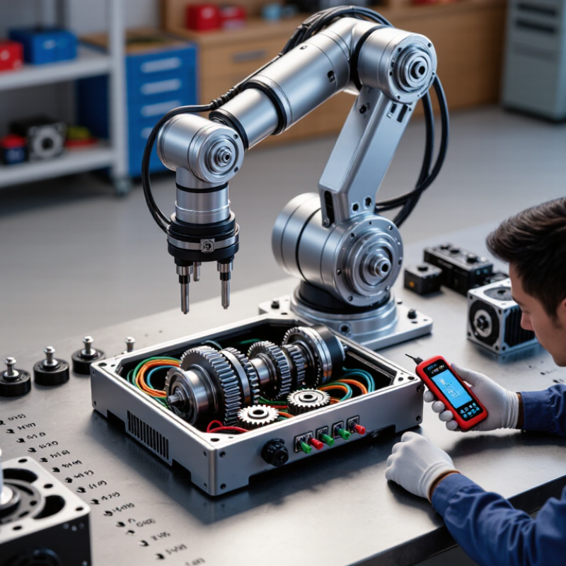
Choosing the right robotic gear motor starts with defining the real payload, not the advertised load. Include the gripper, brackets, cables, and every object carried during motion. A small extra mass can change the motor requirement quickly.
Measure the payload’s distance from the rotation axis. A 2 kg load held 0.3 meters away creates more demanding torque than the same load near the shaft.
For vertical motion, estimate torque with T = mass × gravity × distance. For rotating arms, include inertia, acceleration, friction, and gearbox efficiency. Do not guess inertia. Use CAD data or a measured mass distribution when possible.
After calculating the peak operating torque, apply a 1.5–2× safety factor. A 1.5× factor may suit controlled motion with light impacts. Choose 2× when starts are frequent, loads vary, or the mechanism may stop suddenly. Check torque at the output shaft, not only the motor shaft. Speed matters too; a powerful gearbox can still move too slowly.
Real testing often exposes overlooked details.
Cable drag, cold grease, and uneven surfaces can raise the required torque. I once treated a payload as fixed, then discovered the object shifted during acceleration. The calculation was correct, but the assumption was weak. Test the complete assembly, record current and temperature, and leave room for future wear.
Match Reduction Ratio and Speed: Compare 10:1–100:1 Gearboxes
A 3,000 rpm motor with a 30:1 gearbox delivers about 100 rpm before losses. A 10:1 ratio suits fast conveyors, while 100:1 favors slow lifting or positioning. Do not select a ratio from speed alone. Load inertia, duty cycle, backlash, and startup torque can change the decision.
A gearbox may multiply motor torque, but efficiency reduces the real output. For example, a 0.5 Nm motor and a 50:1 gearbox may produce far less than 25 Nm. Measure acceleration demand and shock loads. I have seen designs fail because engineers trusted steady-state calculations. That mistake is expensive.
The International Federation of Robotics reported 541,302 industrial robot installations in 2023, showing how widely compact motion systems are being deployed. Its World Robotics 2024 service-robot report also recorded approximately 205,000 professional service robots sold in 2023. More robots mean more varied duty cycles, not one universal gearbox choice.
Record temperature, noise, positioning error, and current draw. Higher ratios usually improve holding force, but they can reduce backdrivability and responsiveness. ISO 9283 testing principles can support repeatable robot performance checks. The overlooked detail is maintenance. Grease condition and bearing wear can quietly change output accuracy.
Choosing the correct voltage is a practical decision, not a label-reading exercise. A 12 VDC gear motor fits many compact robots and simpler battery systems. A 24 VDC motor can reduce current for the same power, helping with cable heating and voltage loss. However, the controller, battery, connectors, and safety protection must support that voltage.
Stall current deserves closer attention. It is the current drawn when the shaft cannot turn, such as when a wheel hits a step. Startup current can approach this value briefly. Check the motor’s stall rating, then size the driver above that demand with sensible thermal margin. A motor rated at 5 A stall should not use a driver limited to exactly 5 A. That leaves little room for temperature changes or manufacturing variation.
Measure the real load.
Bench testing helps. Mount the motor with its actual wheel, gearbox, and payload. Record running current on level ground, during acceleration, and during a controlled stop. I have seen a motor draw modest current while moving freely, then exceed expectations when the robot carried an extra battery. That result is easy to miss. It also shows why no-load current is a weak basis for selection. Keep wiring short where possible, use suitable wire thickness, and inspect voltage at the motor terminals under load. A 24 V system may still perform poorly if the battery sags sharply or the connectors add resistance. Allowing too much margin can increase cost and size, but allowing too little may cause repeated driver shutdowns.
When selecting a robotic gear motor, efficiency should be measured under the real working load, not from a no-load datasheet value. A practical target is 70–90% efficiency during normal operation. The U.S. Department of Energy reports that motor-driven systems consume more than half of industrial electricity, so small losses can become significant across thousands of cycles. Record input power, output torque, speed, and duty cycle during a representative test.
Thermal capacity deserves equal attention. A motor may deliver the required torque briefly, then overheat inside a compact robot joint. Measure the housing temperature after repeated acceleration, holding, and reversing cycles. The IEC 60034-1 framework links motor ratings with temperature-rise limits, but gearbox friction, ambient heat, and poor ventilation can reduce actual capacity. Leave practical margin. Tight enclosures often hide heat.
A 70–90% efficiency range is useful, but not sacred. Higher efficiency can increase cost or size, while a smaller motor may suffer from thermal stress. For comparison, use the same voltage, lubricant condition, payload, and test duration. The U.S. Department of Energy’s motor-system guidance also emphasizes system-level losses, including drives, couplings, and transmissions. I have seen a motor pass a short bench test yet fail after continuous cycling. That result deserves investigation, not excuses.
Representative engineering data showing how efficiency and thermal utilization change as motor load increases.
Under continuous operation, select a gear motor that maintains approximately 70–90% efficiency under load. Thermal utilization should remain below 100%; lower values provide more headroom for ambient temperature, duty-cycle changes, and intermittent overloads.
Choosing the right robotic gear motor starts with the axis requirement, not the motor label. Define payload, speed, acceleration, duty cycle, and mounting position. Critical joints should maintain backlash below 1°. Small errors can become visible at the gripper. Measure repeatability under real load, not only during an unloaded bench test.
Check how the gearbox handles shock, vibration, and temperature changes. Hardened gears, supported shafts, and properly sized bearings usually improve service life. Ask for measured backlash data at low and rated torque. Test the motor after several operating cycles. A cool gearbox may become inaccurate after hours of motion. Lubrication matters too. Incorrect grease can increase drag or shorten gear life.
Use feedback when position accuracy matters. An encoder can reveal errors that the gearbox alone cannot correct. Confirm that its resolution matches the mechanical precision you need. Inspect cable routing and connector protection near moving joints.
I once trusted a clean laboratory result, but the mechanism behaved differently after repeated reversals. That experience changed my testing process.
I now record backlash, temperature, noise, and positioning error at several loads. No design is perfect. Manufacturing tolerances, assembly quality, and wear still create uncertainty. Leave practical safety margin in the torque rating, and review the measurements before approving production.
A 3,000 rpm motor with a 30:1 gearbox produces about 100 rpm before losses.
No. Higher ratios can increase holding force and reduce output speed. They may also reduce backdrivability and responsiveness. Load inertia, backlash, and startup torque still matter. I would not choose by ratio alone.
Start with motor torque, then account for gearbox efficiency.
Compare 10:1, 30:1, 50:1, and 100:1 units under the real payload. Record temperature, noise, positioning error, and current draw. Use the actual wheel, gearbox, and mounting arrangement. Bench results may still miss unusual impacts.
A 12 VDC motor can suit compact robots and simple battery systems. A 24 VDC motor may reduce current for the same power. Lower current can reduce cable heating and voltage loss. The controller, battery, connectors, and protection must match.
Stall current occurs when the shaft cannot turn, such as when a wheel hits a step. Startup current may briefly approach that level. A motor rated at 5 A stall needs a driver above 5 A. Exactly 5 A leaves little thermal margin.
Mount the motor with its actual wheel and payload. Measure current on level ground, during acceleration, and during controlled stops. Also inspect voltage at the motor terminals under load. Measure the terminals.
No-load current is a weak basis for choosing a motor. A motor may move freely, then struggle with an added battery. Long wires and weak connectors can cause voltage loss. I would repeat testing after temperature rises.
Choosing the right Robotic Gear Motor begins with a clear understanding of the robot’s payload, movement, and mechanical inertia. Calculate the required torque under realistic operating conditions, then apply a 1.5–2× safety factor to handle acceleration, friction, and unexpected resistance. The reduction ratio should balance speed and force: lower ratios such as 10:1 offer faster motion, while higher ratios up to 100:1 provide greater torque and control. Compare the gearbox options carefully against the robot’s required output speed and load.
Electrical and mechanical performance are equally important. Select a suitable 12 V or 24 VDC power system, and verify that the controller and supply can support the motor’s stall current. Under continuous load, aim for approximately 70–90% efficiency while confirming that the motor and gearbox can dissipate heat safely. For precision applications, evaluate backlash and target less than 1° on critical axes. Finally, consider construction quality, duty cycle, operating environment, and expected service life to ensure dependable long-term performance.